Note
What’s new and when was the last update of this homepage?
November 25 2014:
added 3d-info pictures
added Cathodic Dis-bonding tester
added Wizfi210 Arduino Mega shield
added A4988 steppermotor driver with Bascom-AVR
9 degrees of freedom. Attitude and heading Inertial Measurement Unit
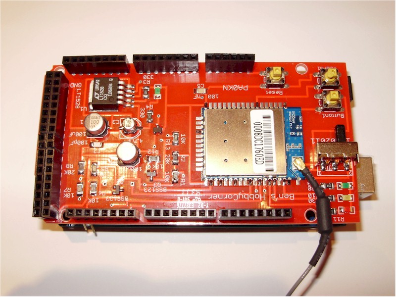
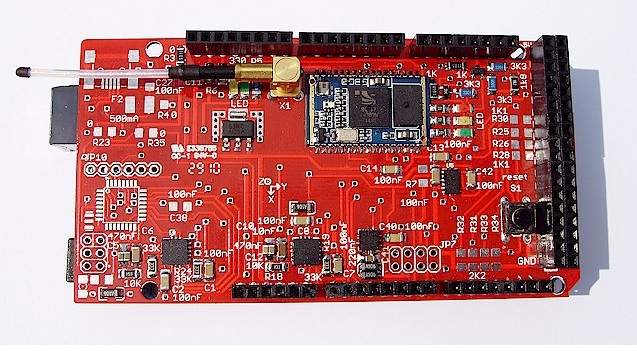
Arduino Mega WizFI210 shield
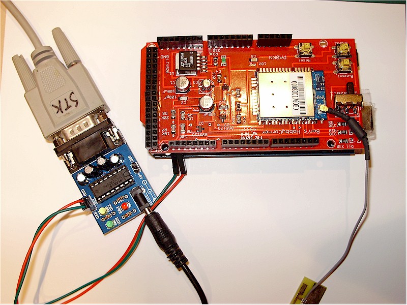
Configuration through a separate RS232-module
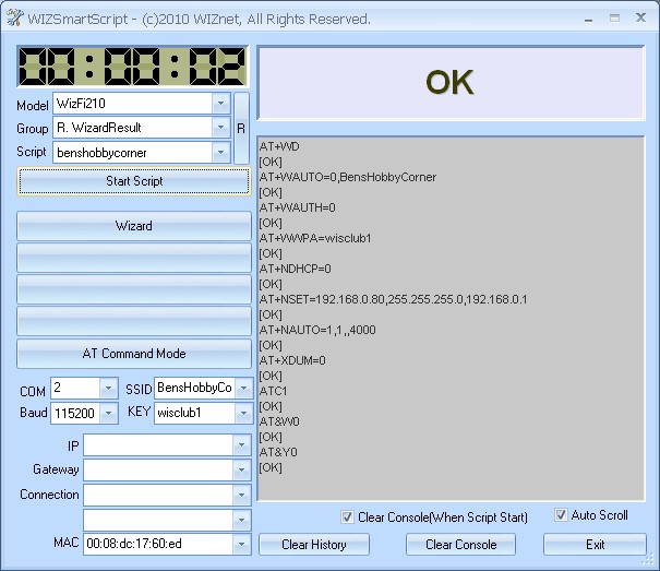
WizSmartScript configuration
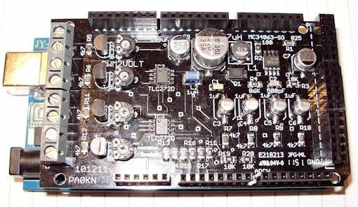
4 channel, 4 x PWM to 0-10 volt (total 350 mA), to drive LED-drivers. PWM2Volt
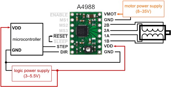
Connection diagram A4988
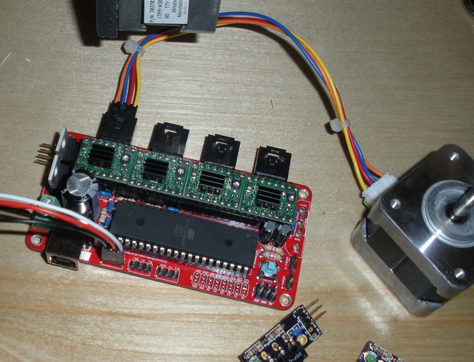
Tested on a Sanguinololu 3D printer controller
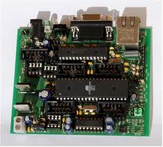
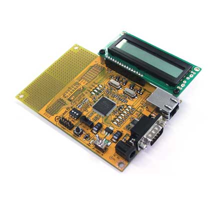
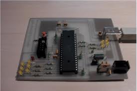
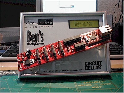
Etherrape with an Atmega644
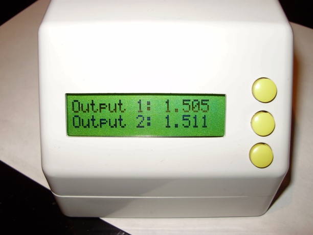
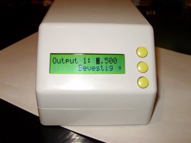
This is a Cathodic Dis-bonding Tester. This device, during a month during test, tests the quality of paint. Two probes. Through the display and three keys the parameters can be filled in, voltage to put on the probes. But it is also web based and can be configured through the Intra/Internet.
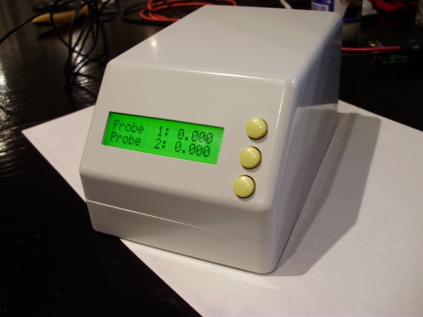
Cathodic Disbonding Tester
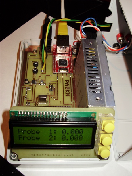
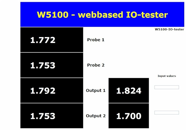
‘Webbased’
FT232RL evaluation board with Visual Basic example
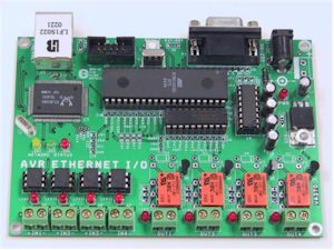
AVR Ethernet board from Hugh Duff
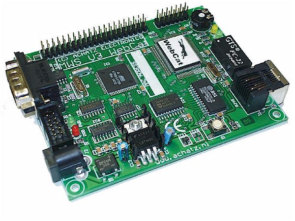
WebCat from www.achatz.nl - Ethernut 1.3F compatible
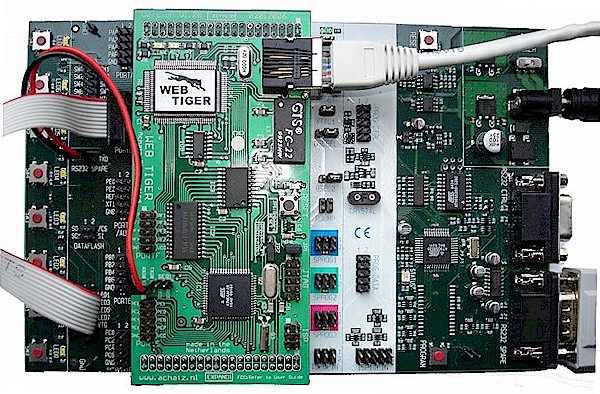
WebTiger - STK500 add-on board with ethernet
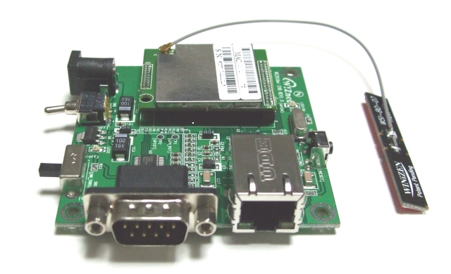
Wiz610wi Wiznet wireless module (it is a small Linux-device)
Long Wiz810mj board on the Embedded Systems Conference in San Jose
Warning
The owner of Ben’s HobbyCorner may update this website without notice. Products specification and usage may change accordingly. The owner of Ben’s HobbyCorner will not be liable for any mis-information or errors found on this website. All software provided on this website is provided ‘AS IS’ without any warranty expressed or implied. The owner of Ben’s HobbyCorner will not be liable for any damages, costs or loss of profits arising from the usage of these hobby products.

.jpg)
.jpg)
.jpg)