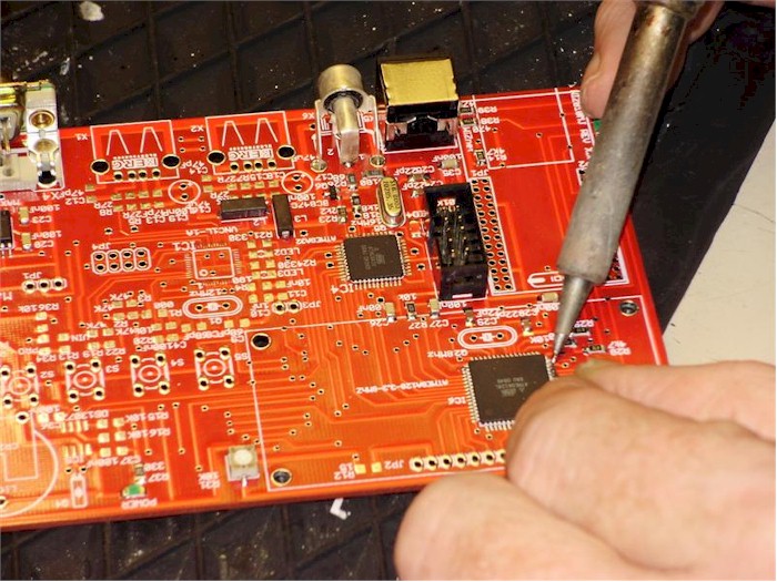
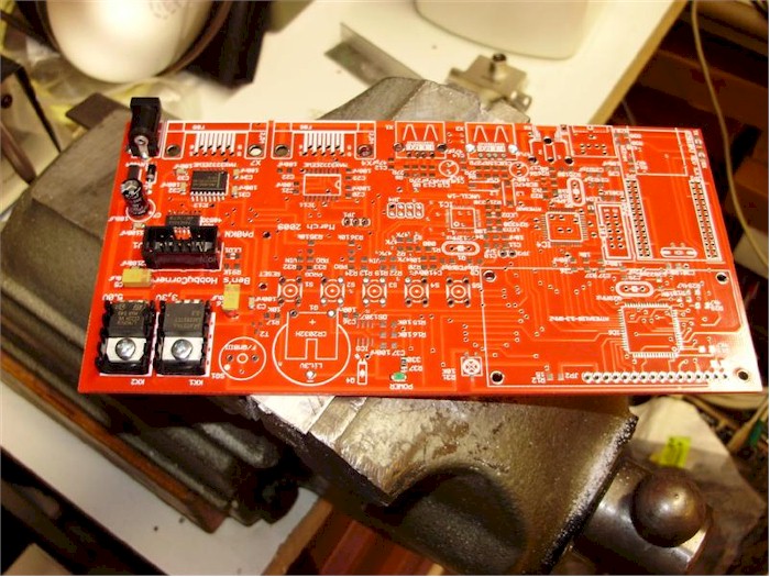
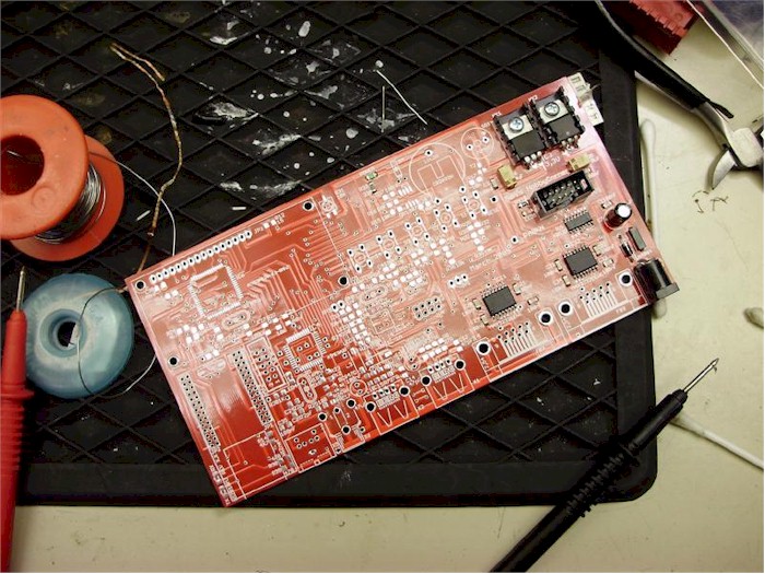
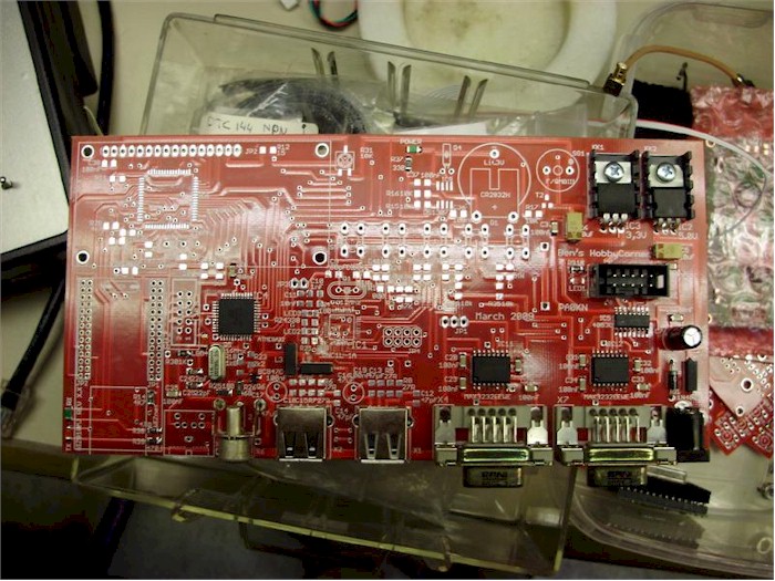
|

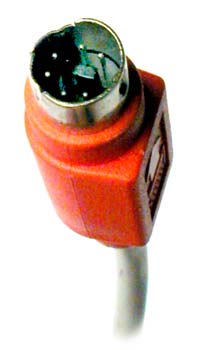
'PS2-keyboard
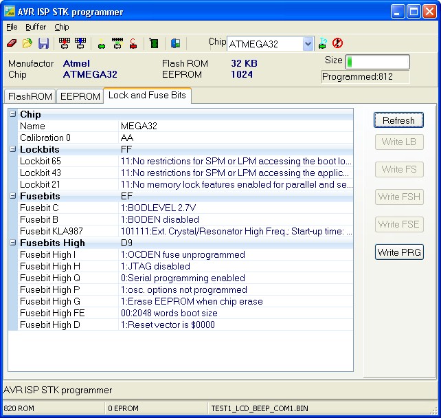
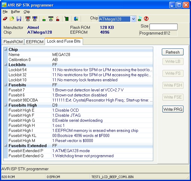
$regfile = "m128def.dat"
$crystal = 8000000
$baud = 9600
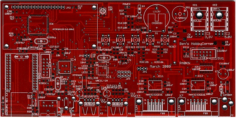
'Hardware
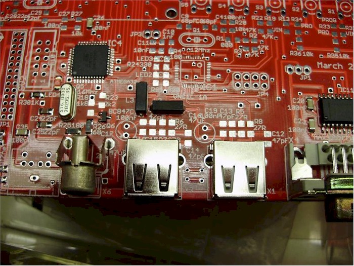
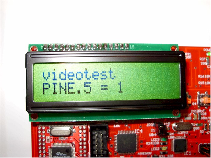
'LCD
'portb.7 LCD Db7
'portb.6 LCD Db6
'portb.5 LCD Db5
'portb.4 LCD Db4
'portb.3 LCD RS
'portb.2 LCD E
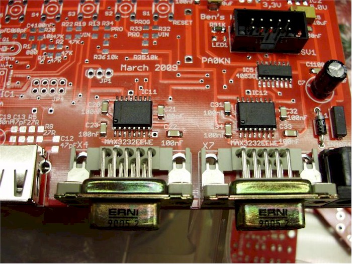
'portd.4 Beeper
'portd.5 Clock keyboard
'portd.6 Data keyboard
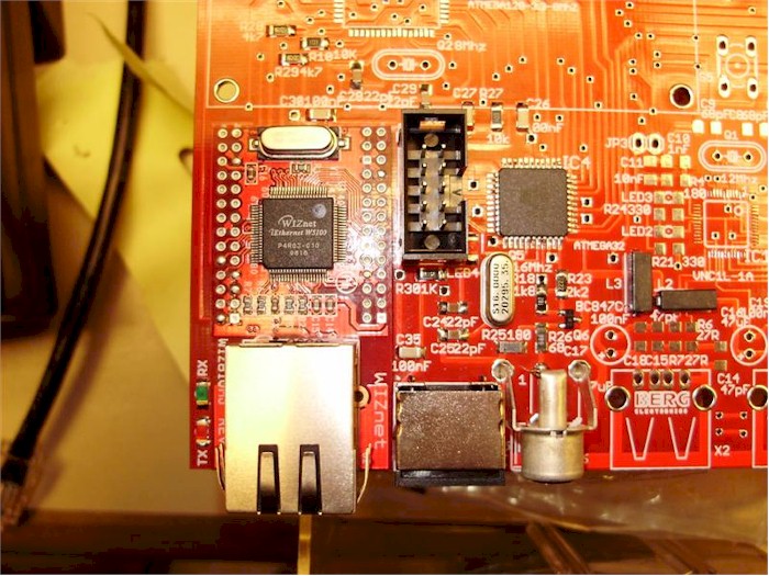
'porte.2 Wiz810MJ reset
'portb.4 Wiz810MJ /scs
'portb.1 SPI SCK
'portb.2 SPI MOSI
'portb.3 SPI MISO
'porte.4 video Puls_RDA
'porte.5 video Acknowledge
'portc.0 video ASCII bit 0
'portc.1 video ASCII bit 1
'portc.2 video ASCII bit 2
'portc.3 video ASCII bit 3
'portc.4 video ASCII bit 4
'portc.5 video ASCII bit 5
'portc.6 video ASCII bit 6
'Portd.4 Beeper
'portd.5 Clock keyboard
'portd.6 Data keyboard
'porte.2 Wiz810MJ reset
'portb.4 Wiz810MJ /scs
'portb.1 SPI SCK
'portb.2 SPI MOSI
'portb.3 SPI MISO
$hwstack = 64 ' default use 32 for the hardware stack
$swstack = 64 ' default use 10 for the SW stack
$framesize = 64 ' default use 40 for the frame space
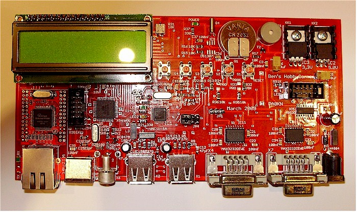
Config Lcdpin = Pin , Db4 = Porta.4 , Db5 = Porta.5 , Db6 = Porta.6 , Db7 = Porta.7 , E = Porta.2 , Rs = Porta.3
Config Lcd = 16 * 2
Cls
Home
'configure the pins to use for the clock and data
'can be any pin that can serve as an input
'Keydata is the label of the key translation table
Config Keyboard = Pind.5 , Data = Pind.6 , Keydata = Keydata
'Dim some used variables
Dim S As String * 100
Dim B As Byte
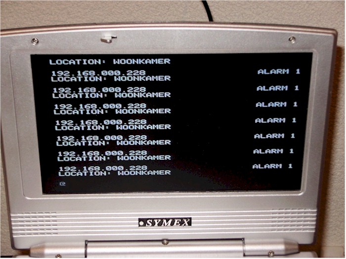
'In this example we use SERIAL(COM) INPUT redirection
$serialinput = Kbdinput
'Show the program is running
Lcd "Keyboard"
Lowerline
Lcd "to com-port"
Do
Input S
Do
B = Getatkbd()
Loop Until B <> 0
'Print B
Loop
End
'Since we do a redirection we call the routine from the redirection routine
'
Kbdinput:
'we come here when input is required from the COM port
'So we pass the key into R24 with the GetATkbd function
' We need some ASM code to save the registers used by the function
$asm
push r16 ; save used register
push r25
push r26
push r27
Kbdinput1:
rCall _getatkbd ; call the function
tst r24 ; check for zero
breq Kbdinput1 ; yes so try again
pop r27 ; we got a valid key so restore registers
pop r26
pop r25
pop r16
$end Asm
'just return
Return
'This is the key translation table
Keydata:
'normal keys lower case
Data 0 , 0 , 0 , 0 , 0 , 200 , 0 , 0 , 0 , 0 , 0 , 0 , 0 , 0 , &H5E , 0 '
Data 0 , 0 , 0 , 0 , 0 , 113 , 49 , 0 , 0 , 0 , 122 , 115 , 97 , 119 , 50 , 0
Data 0 , 99 , 120 , 100 , 101 , 52 , 51 , 0 , 0 , 32 , 118 , 102 , 116 , 114 , 53 , 0 '
Data 0 , 110 , 98 , 104 , 103 , 121 , 54 , 7 , 8 , 44 , 109 , 106 , 117 , 55 , 56 , 0 '
Data 0 , 44 , 107 , 105 , 111 , 48 , 57 , 0 , 0 , 46 , 45 , 108 , 48 , 112 , 43 , 0 '
Data 0 , 0 , 0 , 0 , 0 , 92 , 0 , 0 , 0 , 0 , 13 , 0 , 0 , 92 , 0 , 0 '
Data 0 , 60 , 0 , 0 , 0 , 0 , 8 , 0 , 0 , 49 , 0 , 52 , 55 , 0 , 0 , 0 '
Data 48 , 44 , 50 , 53 , 54 , 56 , 0 , 0 , 0 , 43 , 51 , 45 , 42 , 57 , 0 , 0 '
'shifted keys UPPER case
Data 0 , 0 , 0 , 0 , 0 , 0 , 0 , 0 , 0 , 0 , 0 , 0 , 0 , 0 , 0 , 0 '
Data 0 , 0 , 0 , 0 , 0 , 81 , 33 , 0 , 0 , 0 , 90 , 83 , 65 , 87 , 34 , 0 '
Data 0 , 67 , 88 , 68 , 69 , 0 , 35 , 0 , 0 , 32 , 86 , 70 , 84 , 82 , 37 , 0 '
Data 0 , 78 , 66 , 72 , 71 , 89 , 38 , 0 , 0 , 76 , 77 , 74 , 85 , 47 , 40 , 0 '
Data 0 , 59 , 75 , 73 , 79 , 61 , 41 , 0 , 0 , 58 , 95 , 76 , 48 , 80 , 63 , 0 '
Data 0 , 0 , 0 , 0 , 0 , 96 , 0 , 0 , 0 , 0 , 13 , 94 , 0 , 42 , 0 , 0 '
Data 0 , 62 , 0 , 0 , 0 , 8 , 0 , 0 , 49 , 0 , 52 , 55 , 0 , 0 , 0 , 0 '
Data 48 , 44 , 50 , 53 , 54 , 56 , 0 , 0 , 0 , 43 , 51 , 45 , 42 , 57 , 0 , 0 '
|