 |
Here you can find
some details about the Arduino Mega 9DOF Bluetooth Shield
Work in progress, have to add the tools and some comments.
Last change on
10/17/2014
|
|
|
|
|
|
|
You want a bare PCB? Just email me.
bzijlstra@home.nl
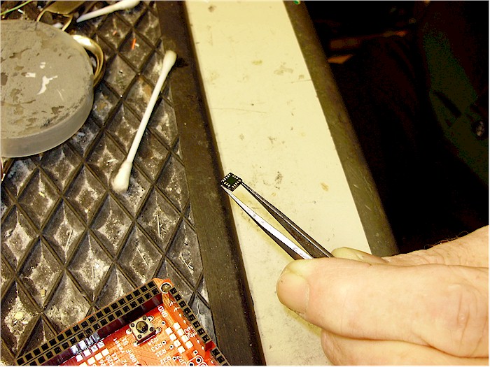
We used these sensors, bought at
www.sparkfun.com
ADXL345, HMC5843, LY530, LPR530 (approx. 52
dollar)
Have used these bluetooth modules, bought
at www.tme.eu
BTM-112 or BTM-222 (approx. 15 dollar)
|
|
|
|
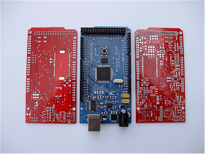
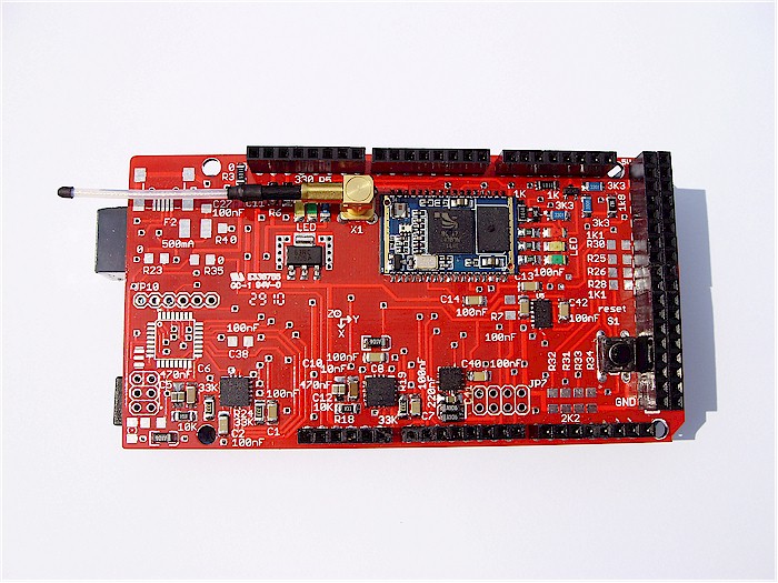
Three combinations of the same board, still one
combination to go.... On the right a complete board with all sensors and
with a Class 2 bluetooth module. On the top a board with just a Class 2
bluetooth module and at the bottom a Class 1 bluetooth board. We are
busy building a fourth one, a standalone one with an Atmega328p on
board.
|
|
|
|
|
|
|
|
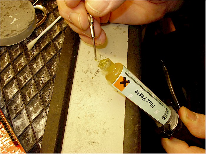
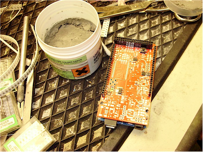
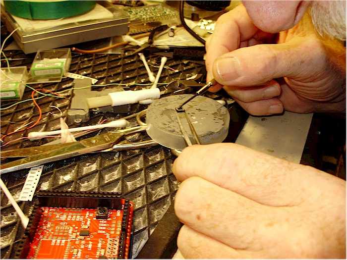
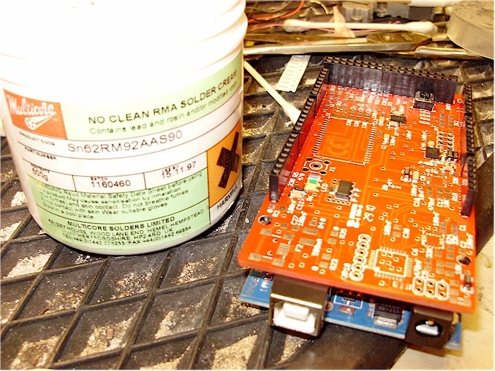
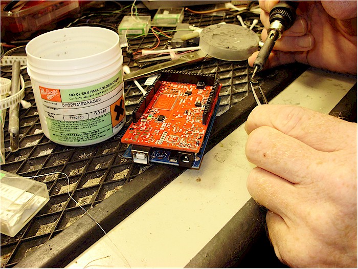
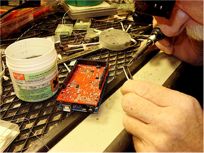
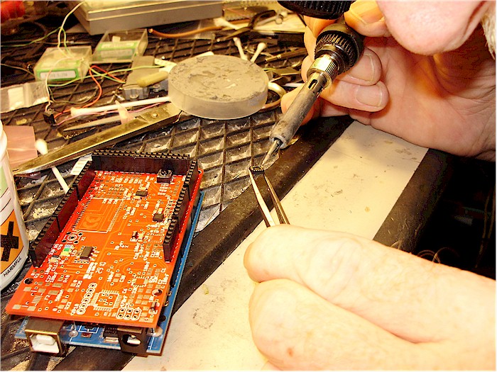
This works great. Mix solder paste with
flux and use this only on the bottom-pads of the sensors.
|
|
|
|
 |
|
|
 |
|
|
 |
|
 |
|
|
 |
|
|
 |
|
|
|

The board can also be used standalone. You
have to put an Atmega328p on the board, USB-connector, FT232RL.
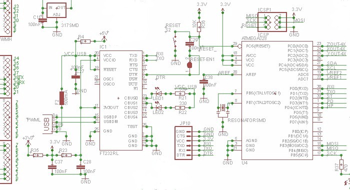
What is the impact on the Arduino Mega
when you mount this shield?
Used are:
SCL (21), SDA (20)
RXD1/TXD1
(19/18 - when using Bluetooth)
Analog 0 - ZOUT-4X, Analog 1 - XOUT-4X,
Analog 3- YOUT-4X
Analog 6 - Vref2, Analog 7 - Vref1
Digital 34 - ST, Digital 33 - PD and Digital 32 - HP.
|
|
|
|
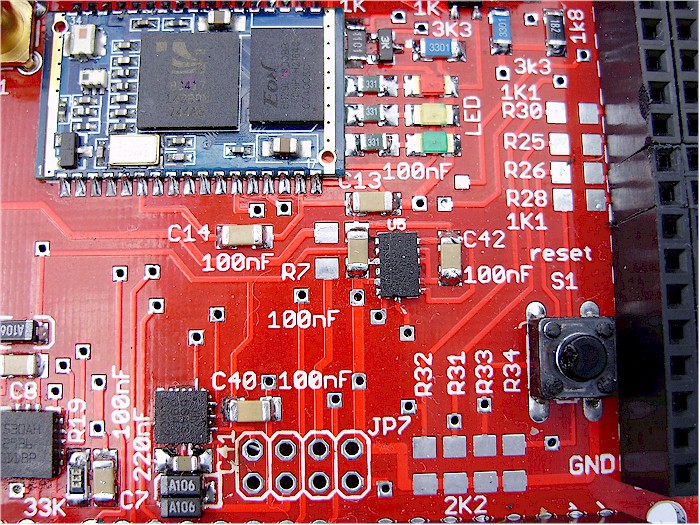
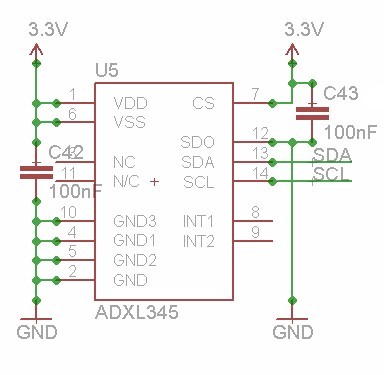
On the right the ADXL345, connected to
the I2c-bus, and when connected well, you will find it in the
I2c-scanner.
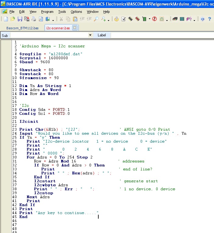
This is the Bascom-AVR code for the
I2c-scanner.
When the ADXL345 and the HMC5843 are fixed on the board you should
see this in Hyperterminal
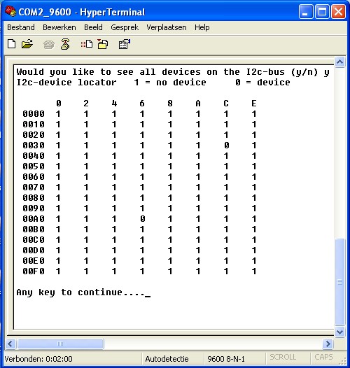
On &HA6 (ADXL345) and on &H3C
(HMC5843) you see your devices.
In the datasheet of the HMC5843 I read
about 7-bit address &H1E,
bit 0 of the 8-bit address of this device is the Read/Write bit.
001 1110 is &H1E but if you put the
Read or the Write bit at the end
you will get 0011 1100 and that is our &H3C
Same for the ADXL345
101 0011 is &H53 but if you add the Read or Write bit
you get 1010 01100 &HA6
|
|
|
|
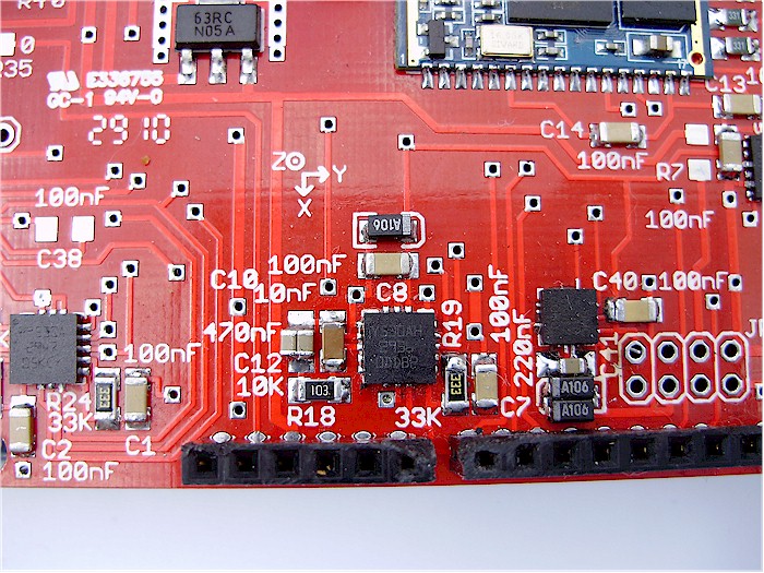 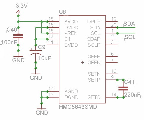
HMC5843 magnetometer on
the right.
When we increased the C9 from 10 uF to 20 uF we have seen a big
improvement.
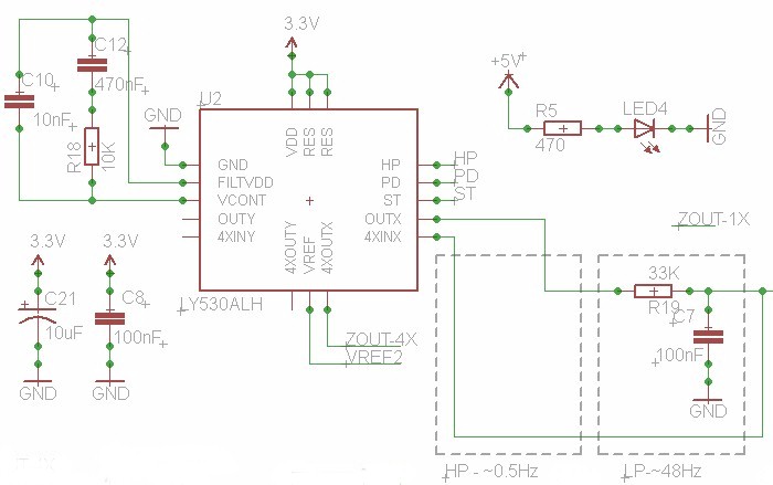
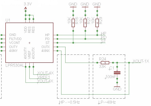
In the middle LY530 - Yaw. |
| |
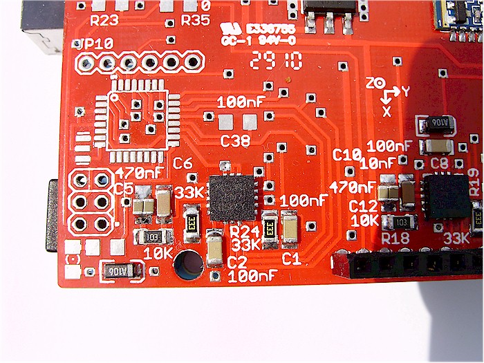
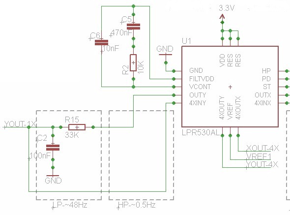
LPR530 - Pitch and Roll.
|
| |
|
 |
|
|
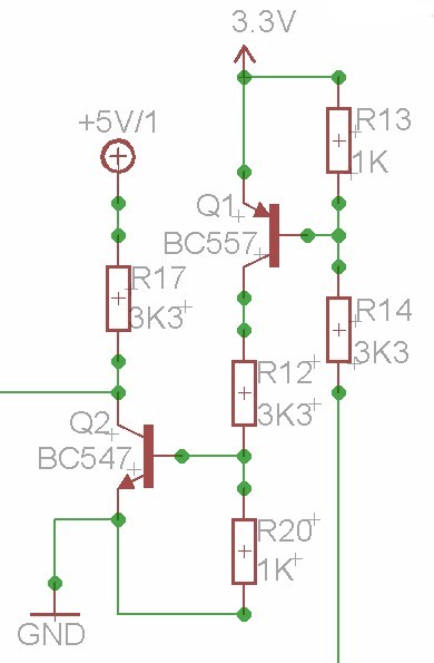
Level conversion is done
between the Arduino Mega RXD1/TXD1 and the BTM-112/BTM-220.
SMD BC848 (NPN) and BC858 (PNP).
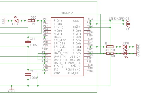
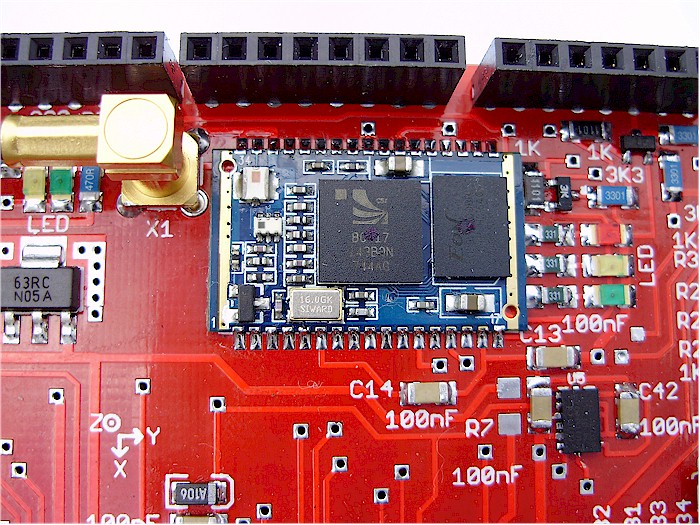
BTM-112 bluetooth Class 2 on top
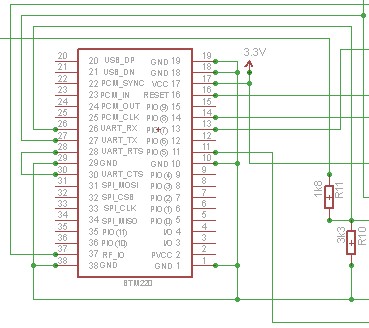
Or, a BTM-220 bluetooth Class 1 on the
bottom |
|
|
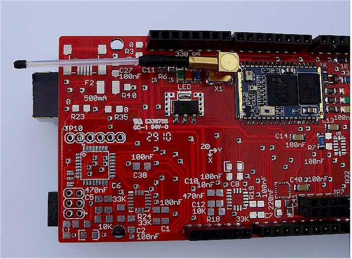
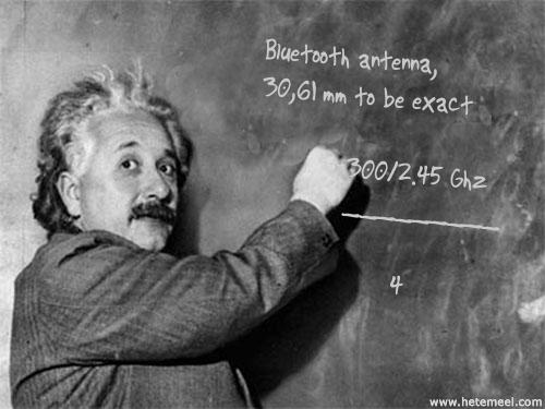
Antenna, 30,61 mm to be exact
|
|
|
|

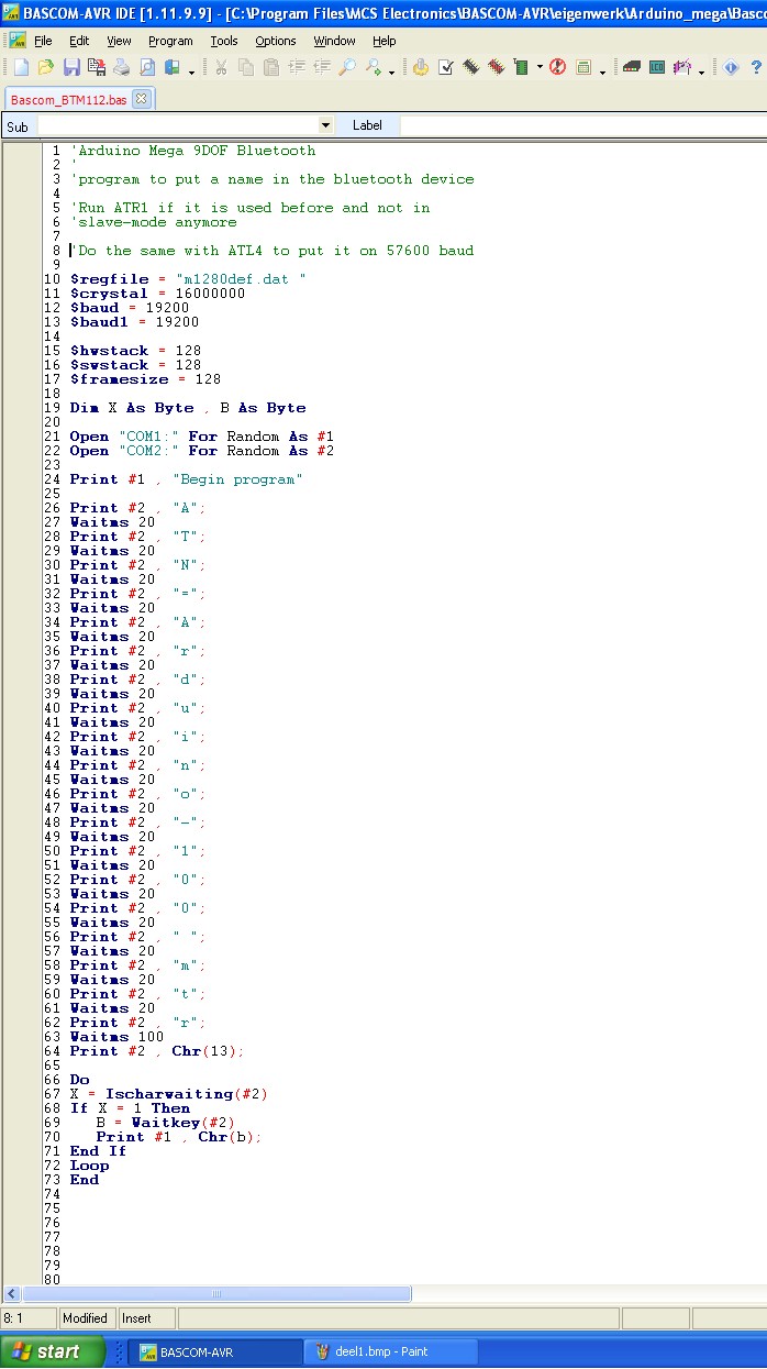
How do you get the name in your
Bluetooth-module? And how do you put it on 57600 baud?
|
|
|
|

|
|
|
|
|
|
|
 |
|
|
|
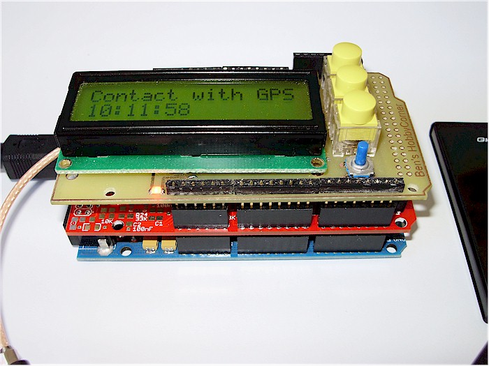
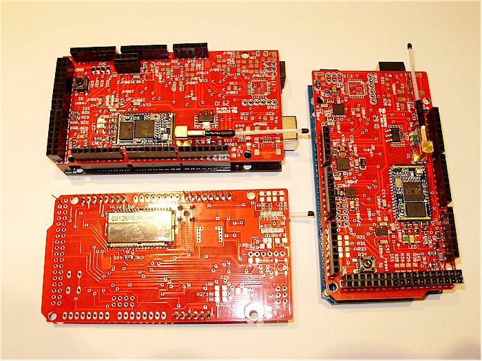
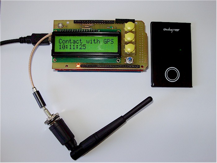
Arduino Mega, 9DOF Bluetooth Shield and on
top a prototype of a LCD Shield.
|
|
|
|
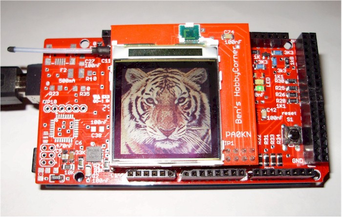
Still two things to work out. A
Nokia 6100 display and a stand-alone 9DOF Bluetooth version.
Well, display working. We had to make a
small DC-DC step-up converter to get about 9 volts for the backlight of
the Nokia 6100. Have tested with the Epson and with the Philips version.
Both working correct.
And here the DC-DC step
up converter in it's place
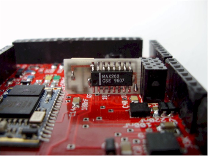
Tested with a
MC34063 the way Sparkfun is doing it's step-up conversion,
but the results with a MAX202 were better. Still have to figure
out, do you
blow-up a MC34063 when there is no load on it's output? |
 |
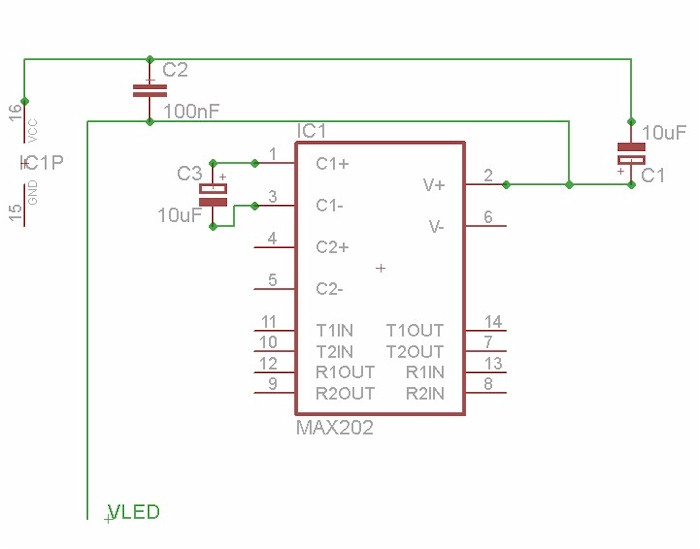
You only need three
capacitors to get the 9.5 volts.
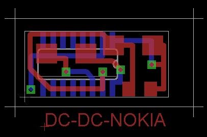
Here the PCB, it is very
SMALL
|
|
|
|
You want to see it at
work? Click on the picture.

|
|
Thanks
to: |
|

Thanks
to Mark Alberts
the creator of Bascom-AVR
www.mcselec.com

Thanks to Natalius
Kiedro
He wrote the Bascom-AVR KixRazor software
Thanks to Theo Kleijn
www.pa0kn.nl

Thanks to Sparkfun
www.sparkfun.com
Flags can be downloaded at
www.3DFlags.com
|
|
Ben
Zijlstra - Ben's HobbyCorner - 2010 |
|