Note
What’s new and when was the last update of this page?
Oktober 22 2014 Bascom-AVR code Master / Slave / Trigger
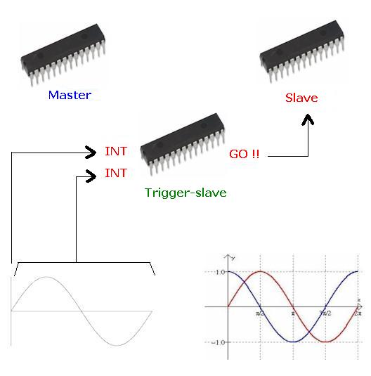
We needed two sinuses of 30 Hertz, one free-running (Master) and another one phase-shifted (Slave). Three AVR’s, can be real small ones, two with an resistor-array to create a DAC. A Master, a Slave and a Trigger_slave. Each time the Master goes through the zero going up, it generates a INT, and another INT is generated on every element of the sinus. In this case build from 256 elements. The interrupts are handled by the trigger_slave. It compares a variable (something that can be changed by a potentiometer on the ADC. or in this case picked from a lookup-table) and every time this variable is the same as the element-counter from the Master, the slave is triggered. And you get a poor men’s phase shifter.
Master a steady 30 hertz signal
 'Master - Free-running 30 Hertz sinus generator

 $regfile = "m88def.dat"
 $crystal = 12000000

 $hwstack = 128
 $swstack = 128
 $framesize = 128

 Config Portd = Output
 Config Portb.1 = Output                                     'toggle by a start of the sinus
 Config Portb.2 = Output                                     'toggle at every element of sinus

'Config Portb.0 = Output

 Dim X As Byte
 Dim Y As Byte

 Do
 Restore Sinus
 For Y = 0 To 255

 Read X
 Portb.1 = 0
 Waitus 2
 Portb.1 = 1
 If Y = 0 Then
 Portb.2 = 0
 Waitus 2
 Portb.2 = 1
 End If
 Portd = X

 'waitus 124   =   30,5 Hz

 Waitus 123                                                  '30 herz with 123 us

 Next Y
 Loop
 End
 Sinus:
 Data &H80 , &H83 , &H86 , &H89 , &H8C , &H8F , &H92 , &H95 , &H98 , &H9C , &H9F , &HA2 , &HA5 , &HA8 , &HAB , &HAE
 Data &HB0 , &HB3 , &HB6 , &HB9 , &HBC , &HBF , &HC1 , &HC4 , &HC7 , &HC9 , &HCC , &HCE , &HD1 , &HD3 , &HD5 , &HD8
 Data &HDA , &HDC , &HDE , &HE0 , &HE2 , &HE4 , &HE6 , &HE8 , &HEA , &HEC , &HED , &HEF , &HF0 , &HF2 , &HF3 , &HF5
 Data &HF6 , &HF7 , &HF8 , &HF9 , &HFA , &HFB , &HFC , &HFC , &HFD , &HFE , &HFE , &HFF , &HFF , &HFF , &HFF , &HFF
 Data &HFF , &HFF , &HFF , &HFF , &HFF , &HFF , &HFE , &HFE , &HFD , &HFC , &HFC , &HFB , &HFA , &HF9 , &HF8 , &HF7
 Data &HF6 , &HF5 , &HF3 , &HF2 , &HF0 , &HEF , &HED , &HEC , &HEA , &HE8 , &HE6 , &HE4 , &HE2 , &HE0 , &HDE , &HDC
 Data &HDA , &HD8 , &HD5 , &HD3 , &HD1 , &HCE , &HCC , &HC9 , &HC7 , &HC4 , &HC1 , &HBF , &HBC , &HB9 , &HB6 , &HB3
 Data &HB0 , &HAE , &HAB , &HA8 , &HA5 , &HA2 , &H9F , &H9C , &H98 , &H95 , &H92 , &H8F , &H8C , &H89 , &H86 , &H83
 Data &H80 , &H7C , &H79 , &H76 , &H73 , &H70 , &H6D , &H6A , &H67 , &H63 , &H60 , &H5D , &H5A , &H57 , &H54 , &H51
 Data &H4F , &H4C , &H49 , &H46 , &H43 , &H40 , &H3E , &H3B , &H38 , &H36 , &H33 , &H31 , &H2E , &H2C , &H2A , &H27
 Data &H25 , &H23 , &H21 , &H1F , &H1D , &H1B , &H19 , &H17 , &H15 , &H13 , &H12 , &H10 , &H0F , &H0D , &H0C , &H0A
 Data &H09 , &H08 , &H07 , &H06 , &H05 , &H04 , &H03 , &H03 , &H02 , &H01 , &H01 , &H00 , &H00 , &H00 , &H00 , &H00
 Data &H00 , &H00 , &H00 , &H00 , &H00 , &H00 , &H01 , &H01 , &H02 , &H03 , &H03 , &H04 , &H05 , &H06 , &H07 , &H08
 Data &H09 , &H0A , &H0C , &H0D , &H0F , &H10 , &H12 , &H13 , &H15 , &H17 , &H19 , &H1B , &H1D , &H1F , &H21 , &H23
 Data &H25 , &H27 , &H2A , &H2C , &H2E , &H31 , &H33 , &H36 , &H38 , &H3B , &H3E , &H40 , &H43 , &H46 , &H49 , &H4C
 Data &H4F , &H51 , &H54 , &H57 , &H5A , &H5D , &H60 , &H63 , &H67 , &H6A , &H6D , &H70 , &H73 , &H76 , &H79 , &H7C
 Data &H0B
Slave triggered 30 hertz sinus
'Slave - triggered 30 Hertz generator

$regfile = "m88def.dat"
$crystal = 12000000

$hwstack = 64
$swstack = 64
$framesize = 64

Config Portd = Output
Config Portb.1 = Input                                      'trigger
Portb.1 = 1                                                 'pull-up

Dim X As Byte

Do
Restore Sinus

Bitwait Pinb.1 , Reset                                      'wait for trigger

Do
Read X
If X = &H0B Then
Exit Do
End If
Portd = X

'waitus 124   =   30,5 Hz

Waitus 126                                                  '29 hertz
Loop

Loop

End

Sinus:
Data &H80 , &H83 , &H86 , &H89 , &H8C , &H8F , &H92 , &H95 , &H98 , &H9C , &H9F , &HA2 , &HA5 , &HA8 , &HAB , &HAE
Data &HB0 , &HB3 , &HB6 , &HB9 , &HBC , &HBF , &HC1 , &HC4 , &HC7 , &HC9 , &HCC , &HCE , &HD1 , &HD3 , &HD5 , &HD8
Data &HDA , &HDC , &HDE , &HE0 , &HE2 , &HE4 , &HE6 , &HE8 , &HEA , &HEC , &HED , &HEF , &HF0 , &HF2 , &HF3 , &HF5
Data &HF6 , &HF7 , &HF8 , &HF9 , &HFA , &HFB , &HFC , &HFC , &HFD , &HFE , &HFE , &HFF , &HFF , &HFF , &HFF , &HFF
Data &HFF , &HFF , &HFF , &HFF , &HFF , &HFF , &HFE , &HFE , &HFD , &HFC , &HFC , &HFB , &HFA , &HF9 , &HF8 , &HF7
Data &HF6 , &HF5 , &HF3 , &HF2 , &HF0 , &HEF , &HED , &HEC , &HEA , &HE8 , &HE6 , &HE4 , &HE2 , &HE0 , &HDE , &HDC
Data &HDA , &HD8 , &HD5 , &HD3 , &HD1 , &HCE , &HCC , &HC9 , &HC7 , &HC4 , &HC1 , &HBF , &HBC , &HB9 , &HB6 , &HB3
Data &HB0 , &HAE , &HAB , &HA8 , &HA5 , &HA2 , &H9F , &H9C , &H98 , &H95 , &H92 , &H8F , &H8C , &H89 , &H86 , &H83
Data &H80 , &H7C , &H79 , &H76 , &H73 , &H70 , &H6D , &H6A , &H67 , &H63 , &H60 , &H5D , &H5A , &H57 , &H54 , &H51
Data &H4F , &H4C , &H49 , &H46 , &H43 , &H40 , &H3E , &H3B , &H38 , &H36 , &H33 , &H31 , &H2E , &H2C , &H2A , &H27
Data &H25 , &H23 , &H21 , &H1F , &H1D , &H1B , &H19 , &H17 , &H15 , &H13 , &H12 , &H10 , &H0F , &H0D , &H0C , &H0A
Data &H09 , &H08 , &H07 , &H06 , &H05 , &H04 , &H03 , &H03 , &H02 , &H01 , &H01 , &H00 , &H00 , &H00 , &H00 , &H00
Data &H00 , &H00 , &H00 , &H00 , &H00 , &H00 , &H01 , &H01 , &H02 , &H03 , &H03 , &H04 , &H05 , &H06 , &H07 , &H08
Data &H09 , &H0A , &H0C , &H0D , &H0F , &H10 , &H12 , &H13 , &H15 , &H17 , &H19 , &H1B , &H1D , &H1F , &H21 , &H23
Data &H25 , &H27 , &H2A , &H2C , &H2E , &H31 , &H33 , &H36 , &H38 , &H3B , &H3E , &H40 , &H43 , &H46 , &H49 , &H4C
Data &H4F , &H51 , &H54 , &H57 , &H5A , &H5D , &H60 , &H63 , &H67 , &H6A , &H6D , &H70 , &H73 , &H76 , &H79 , &H7C
Data &H0B
Trigger chip (made use of the master chip of this project)
$regfile = "m128def.dat"
$crystal = 16000000

$hwstack = 128
$swstack = 128
$framesize = 128

Dim X As Byte
Dim Y As Byte

Y = 128                                                     '180 degrees phase-shift

Trigger_slave Alias Porte.2
Config Trigger_slave = Output

Config Int7 = Falling                                       '0-crossing of Master
On Int7 Isr_routine

Config Int4 = Falling                                       'each element of Master sinus
On Int4 Isr_routine2

Enable Int4
Enable Int7
Enable Interrupts

Do
Loop
End


Isr_routine2:                                               'each element of Master sinus                      '
If X = Y Then
Reset Trigger_slave
Waitus 2
Set Trigger_slave
End If
Incr X
Return

Isr_routine:                                                '0-crossing of Master
X = 0
Return
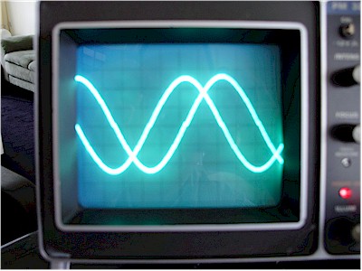
90 degrees
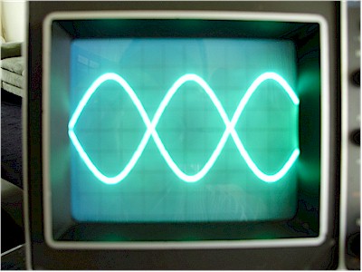
180 degrees
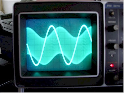
The VOR testsignal, 9960 Khz subcarrier 30 Hertz frequency-modulated
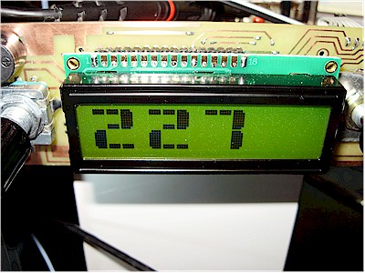
227 degrees. Thanks to YO6PIR for the Huge Bascom-AVR 16 x 2 LCD character routines.
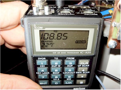
227 degrees on a VOR-receiver
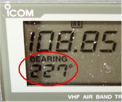
close-up of 227 degrees on a VOR-receiver
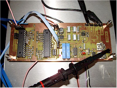
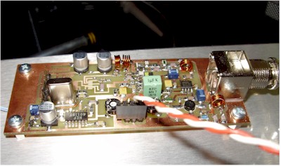
Master/slave PCB
receiver PCB